| Surface Water-Groundwater Interaction | |
| Surface Water-Groundwater Interaction | |
| Modelling Interaction Between Unconfined Groundwater and Surface Water Bodies in Aquifers Subjected to Periodic Forcing | |||||||
|
![]()
1. Introduction and Objective
Cyclic responses to
periodic sinusoidal forcing are well documented in the study of
groundwater systems, however there are few results in 2D or 3D.
The objective of this research is to understand the dynamics of
groundwater flow in a 2D vertical section beneath a wide shallow
lake in a regional aquifer. Full details are presented in Smith
(1999).
2. Background
Nield et al. [1994] identified 39 fundamentally different groundwater flow patterns as a function of water body geometry and the relative magnitude of aquifer flows and net recharge to the water table. Steady flow patterns were classified as being recharge, discharge or flow-through.
Townley [1995] presented analytical solutions for the response of 1D aquifers to periodic forcing.
Two further papers by Townley [in press] present analytical solutions for a 1D aquifer-lake-aquifer system, and a periodic finite element model called AQUIFEM-P for computing periodic fluctuations in heads and velocities in a 2D region.
This presentation
introduces ongoing research that uses AQUIFEM-P, with special
mixed boundary conditions developed from Townley [1995], to
simulate 2D flow patterns beneath a lake in a regional setting.
It generalises the 1D aquifer-lake-aquifer results to 2D in the
near field of a surface water body, and allows us to determine
the extent to which the steady results obtained by Nield et
al. [1994] can be applied to dynamic systems.
3. Notation
For reasons of convenience, complex notation is used to represent sinusoidal variation. In general
f(t) = fs + Re{fp exp(i w t)}
where fs
is the steady-state or mean value of f(t) and fp
= fr + i fi
is the complex amplitude of fluctuation. The amplitude and phase
are the modulus |fp| and argument
arg(fp), respectively.
"Re{...}" is an operator that returns the real part of
a complex number, i = sqrt(-1) and w = 2p / P is the angular frequency of period P.
4. Conceptual Model and Solution Technique
Consider a cross-section through an aquifer, with groundwater flowing from a groundwater divide towards an ocean boundary (Figure 1a).
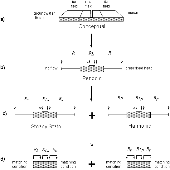 |
| Figure 1 - Problem decomposition |
Because flow in the far field is essentially horizontal, we assume that these regions can be represented by 1D models with a transmissivity T that is spatially varying but constant in time (Figure 1b). The near field is approximated as a rectangular region, following Nield et al. [1994]. The fact that the upper surface is horizontal and fixed in time is a geometric approximation which still allows many features of the true solution to be studied.
Because the equations to be solved in the 1D and 2D regions are linear, we separate the response of the system into two parts: a steady solution, and a harmonic (purely sinusoidal) solution (Figure 1c). We use the analytical solutions of Townley [1995] to develop 3rd Type (mixed) boundary conditions at the ends of the 2D near field, such that these boundary or matching conditions encapsulate the steady and harmonic behaviour of the far field (Figure 1d). We solve both steady and harmonic problems in 2D using AQUIFEM-P, and then use visualisation techniques to show pathlines and streaklines beneath the surface water body. All results are presented in terms of key non-dimensional ratios (Appendix 1). The lake-aquifer geometry and boundary fluxes are depicted in Figure 2; aquifer properties include the horizontal and vertical components of hydraulic conductivity (Kx, Kz), specific yield (Sy), specific storativity (S0), and the period of fluctuations is P.
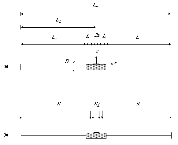 |
| Figure 2 - Dimensional Analysis: (a) geometry, (b) boundary fluxes |
5. Results
Because heads have steady and harmonic components, specific discharge and velocity also have both steady and harmonic components, in both x and z directions. Harmonic variations in velocities result in velocity and displacement ellipses (Figure 3), with a displacement ellipse being the same shape and orientation as the velocity ellipse but scaled in magnitude by a factor of P/2p or 1/w.. When superimposed on steady flow, these result in pathlines of three kinds: smooth wavy pathlines, cuspy pathlines (with particles passing through instantaneous stagnation points) and loopy pathlines (Figure 4).
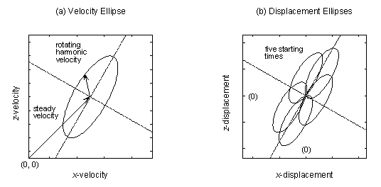 |
| Figure 3 - Velocity and displacement ellipses in harmonic flow |
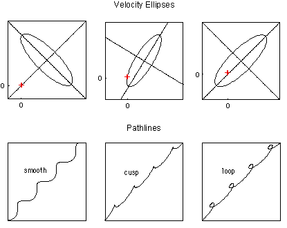 |
| Figure 4 - Types of pathlines in periodic flow |
We have been keen to find out under what circumstances we would find complex cuspy or loopy flowlines in the real world. Systematic searching in the non-dimensional parameter space has started to provide some indications.
Figures 5 and 6 show ellipses for lake-aquifer systems that are aquifer-driven and lake-driven, respectively. In Figure 5, the dominant fluctuation is backwards and forwards in the aquifer, with a flow-through fluctuation through the lake. In Figure 6, the dominant fluctuation is into and out of the aquifer, with the lake alternating between recharge and discharge behaviour. In both cases, ellipses are open only for intermediate values of Lr2Sy/KxBP (i.e. for aquifer response times which are of the same order as the period of fluctuations), and for large values of |Rp|P/SyB (i.e. when the fluctuation in water table due to recharge fluctuations is significant relative to aquifer thickness). While these results may be intuitively reasonable, they have not previously been described in quantitative terms.
|
|||||||||||||||||||||||||||||||||||
| Figure 5 - Aquifer-driven harmonic fluctuations in groundwater flow (for enlarged view click on individual pictures) |
|
|||||||||||||||||||||||||||||||||||
| Figure 6 - Lake-driven harmonic fluctuations in groundwater flow (for enlarged view click on individual pictures) |
Consider a steady flow pattern with groundwater discharge toward the lake. In Nield et al.'s [1994] classification this system would be described as a discharge regime of type D4 (Figure 7a). With different sinusoidal recharge to the lake and aquifer, AQUIFEM-P predicts velocity and/or displacement ellipses as shown in Figure 7b. Superimposing the steady and fluctuating velocity fields and starting particles at a number of times through a period shows that particles can be completely captured by the lake (Figure 7c), or they can migrate from the lake into the lake's release zone (Figure 7d), or they can appear to be released by the lake, only to be recaptured at a later time (Figure 6e).
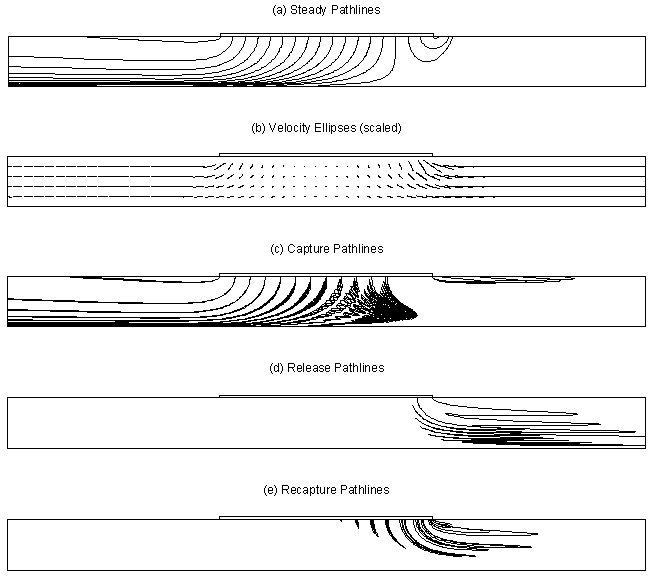 |
| Figure 7 - Pathline beneath a
lake with sinusoidal fluctuation in recharge (click here to see these results animated) |
6. Discussion and Conclusions
Groundwater flow patterns beneath surface water bodies during periods of dynamic changes in water levels may be much more complex than previously realised. The complex advective flow patterns beneath surface water bodies may be responsible for effects that would commonly be described as mixing or dispersion.
A sinusoidal dynamic is one of the simplest to deal with mathematically, thus AQUIFEM-P provides a versatile tool for studying the details of flow patterns in vertical section. Special mixed boundary conditions at the ends of the near field, allow AQUIFEM-P to account for regional behaviour.
Appendix 1 - Non-dimensional Ratios
| Variable Ratios | |
| 2a / B | Geometric ratio relating the size of the lake to the saturated thickness of aquifer. |
| 2a / Lr | Geometric ratio relating the size of the lake to the length of the regional aquifer. |
| LL / Lr | Geometric ratio describing the position of the lake within the regional setting. |
| RLs / Rs | Recharge flux ratio; relates steady state lake recharge to steady aquifer recharge. |
| |RLp|Sy / |Rp| | Recharge amplitude ratio; relates the amplitude of fluctuation in lake recharge to the amplitude of fluctuation in aquifer recharge. |
| Lr2Sy / KxBP | Non dimensional response time; describes the ability of the lake-aquifer system to respond to, or propagate, periodic forcing applied at the boundaries. Equal to the response time of the aquifer divided by the period of fluctuation. |
| RsLr2 / KxB2 | Non dimensional 'mound' height; a measure of the height of the regional groundwater mound. Equal to the total aquifer recharge divided by the ability of the aquifer to 'carry' it away (i.e. transmissivity KxB, times a gradient B/Lr - allowing for a head B drop over a distance Lr). |
| |Rp|P / SyB | Non dimensional scale ratio; describes the magnitude of the harmonic response |Rp|P / Sy , relative to the depth of aquifer B. |
| arg(RLp / Rp) | Recharge phase lag; describes the phase difference between fluctuations in lake recharge and fluctuations in aquifer recharge. |
| Sy | Aquifer specific yield. |
| Constrained Ratios | |
| L / B = 2 | Geometric ratio relating the length of the near field to the aquifer depth; chosen so that vertical flow effects induced by the lake are negligible at the near field boundaries. This implies that and are approximately uniform with depth. |
| Kx / Kz = 1 | Anisotropy ratio; equal to one for isotropic conditions in this work. |
| SoB = 0 | Aquifer elastic storage coefficient; assumed negligibly small in a phreatic aquifer. |
| arg(Rp) = 0 | Phase of aquifer recharge; provides a time datum for measuring the phase of fluctuations. |
References
Nield SP. Townley LR. Barr AD. 1994. A framework for quantitative analysis of surface water - groundwater interaction: Flow geometry in a vertical section. Water Resources Research 30(8), 2461-2475.
Smith AJ. 1999. Periodic forcing of surface water-groundwater interaction; modelling in vertical section. PhD Thesis, Murdoch University, Western Australia, 259 pp.
Townley LR. 1995. The response of aquifers to periodic forcing. Advances in Water Resources 18(3), 125-146.
Copyright © 2018 by GW-SW |